EN

19 Years Rigid PCB Manufacturer

Equipped with advanced automatic machines, QCX ELECTRONIC CO., LIMITED is capable of providing cost-effective PCB boards with high-quality standards and quick delivery time. Our engineer team is consist of 28 experienced engineers standing by here to offer solutions to all kinds of PCB boards, including single-layer PCB, double-sided PCB, multi-layer PCB with different materials. 

We’re pleased to offer any help on your PCB design inspection, PCB fabrication, pcb assembly.

Services
0 +
SQM/month
0 %+
IncreasingRate

What Is Rigid PCB?

Today, the printed circuit board is a very valuable element. So what is PCB for you and what does it do? What are the PCB (Printed Circuit Board) types and usage areas? We have researched it in detail and compiled it for you.

Printed circuit boards are formed by melting a part of the copper surface to the printed circuits found in most electronic systems, and the circuit elements are connected via copper tracks. Therefore, printed circuit board systems are very important and frequently used systems.

A rigid PCB is a Print Network Board that is Rigid and cannot be folded or is not flexible. Rigid PCB is made of a dense and rigid substrate material such as fiberglass so it is deliberately made not to be folded or bent.

 What are the Advantages of rigid Printed Circuit Boards?

Printed circuit boards have two important purposes. First of all, it is generally to keep the electronic components together or to provide the electrical connection between the components. The card itself is insulating and in a rigid material.

These thin general connections that can be seen on the surface of the card are also part of the conductive foil covering the whole card at the beginning of the production stages. In addition, this conductive foil on the printed circuit boards is partially hollowed out and the remaining copper paths form a mesh.

Printed circuit boards have many advantages. These; the physical dimensions and surface areas of electronic devices are getting smaller. In addition, some mass production of electronic circuits is accelerated or facilitated.

Since wire-shaped conductors are not used in the circuits, the distortion co-electrical noise is reduced in generally high-frequency circuits. Since the elements of electronic circuits are generally simplified, construction or repair becomes easier.

Structure and Production of PCB

PCB is the ‘brains’ of electronic devices that we encounter everywhere in our lives in today’s technology. More descriptively, we call the electronic components, that is, the conductive boards that hold the components together, PCB. Its main purpose is to make cumbersome and complex circuits more open and easily adjustable.

Today, when PCB is mentioned, devices such as computers and keyboards come to mind for most of us. But BDKs is the basic building block of every electronic device, from the military industry to the automotive industry, from medicine to home. PCBs also vary. Prime examples of this diversity are single or multi-layer PCBs, rigid or Flex PCBs.

Structure

Let’s consider the simplest one, a single-layer PCB. Single-layer circuit boards consist of 3 different layers.

  1. First, the copper plate that provides the electricity flow between the components of the circuit board
  2. Secondly, the solder mask, which prevents communication for unwanted components and prevents soldering errors
  3. Finally, there is the screen printing layer on which you can write the texts of what the components are or your brand logo.

Material

Material characteristics for rigid printed circuit boards that must be taken into account:

  • dimensional stability;
  • heat resistance (soldering without destruction and reduction of flexibility);
  • tear resistance;
  • acceptable electrical properties;
  • flexibility at extreme temperatures;
  • low water absorption (stratification, exfoliation when heated);
  • chemical resistance (during production and use);
  • incombustibility;
  • General requirements (stability of characteristics, multiple sources of supply, cost, amount of required material in a product, etc.).
Quality Control

Board Design Inspection

In foreign practice, the rules for joint step-by-step work of a designer and a technologist have already been formed:

  • ensuring manufacturability – Design for Manufaclurability (DfM);
  • assembly support – Design for Assembly (DFA);
  • ensuring testability – Design for Testability (DfT)
  • ensuring reliability – Design for Reliability (DfR).

Why pre- designing is important in rigid pcb?

However, the board design is often geographically and organizationally separated from the manufacturer. Therefore, starting from the early stages of the project, it is necessary to establish close contact with the manufacturer to optimize the product design and the suitability of the project for production. 

Requirements for these processes of interaction of all enterprise services in the design and manufacture of electronics are laid down in foreign standards, in particular, in IPC-A-620, ANS1 / J-STD-001, IPC-SM ~ 785, IPC-D-279.

Manufacturing of Rigid PCB

It is necessary to check with the printed circuit board manufacturer the presence or availability of construction materials planned for use in the project, and their technological compatibility in the manufacture of the product.

 Of great importance is the possibility of multiplying the boards on the workpiece and the choice of the optimal size of the workpiece, since this determines the consumption of construction and technological materials, and therefore the cost of the products.

Before starting the development of a serial product, it is necessary to clarify with the manufacturer what dimensions of multi-workpieces (rigid dielectric with a metal layer on which the maximum possible number of rigid printed circuit boards is located) can be processed on technological equipment and what is the size of the working area on the workpiece. 

The efficiency of the use of group workpieces becomes important when the volume of production increases. The cost of the board will be lower; more modules can be placed on the workpiece and subjected to group processing. It is necessary to check with the manufacturer the width and length of the roll of material available to him, since, depending on the thickness of the material and the type of equipment, the dimensions of the blanks can vary significantly.

The following factors should be taken into account in rigid pcb manufacturing:

  • distance between elements;
  • the presence of test points that allow you to control the technological process and the resistance of the conductors;
  • mounting holes;
  • reference points;
  • distance between modules;
  • multiplication possibilities;
  • Requirements for the presence of a frame for metalizing holes.

The manufacturing process of rigid pcb

1. The minimum radius of rounding of corners of a contour of rigid boards

1.1 Cutouts in the corners of the flex board to prevent tearing

Experience shows that the main mistakes in the development of dynamic rigid boards are associated with the underestimation of the importance of the competent design of the board outline. Projects come with too small a corner radius, no reinforcements in inner corners, and cutouts. The reduced strength of flex board materials is not taken into account.

The minimum radius at the inner corners of the board outline should be 1.6 mm. However, a larger radius provides higher product reliability and better tear resistance. Additional materials may need to be added to the interior corners to provide improved tear resistance.

 The most effective is the use of non-etched copper foil and additional fastening of loops, where their flexibility is not used.

1.2 Reinforcing the edges and corners of the contour of rigid boards with copper

All cuts and notches must end with a hole with a diameter of 1.5 mm or more. This is especially important when adjacent flex board parts must move independently.

2. Distance from hole to board edge

2.1 Distance standards

The minimum distance between the outer edge of the board and the inner edge of a non-plated hole (or internal cutouts) must be at least 0.5 mm. The location, dimensional tolerances, and contour machining must be taken into account.

The minimum distance from the edge of the transition (between the flexible and rigid parts) to the inner edge of the metalized hole or the edge of the release in the inner layer should not be less than 1.9 mm.

2.2 The thickness of different parts of the rigid pcb board

Rigid parts of multilayer flex and flex-rigid boards must be of the same thickness to ensure correct hole plating. Sequential lamination or different thicknesses increase manufacturing costs.

It is highly undesirable to lay different thicknesses for several rigid parts. This can not only increase the cost and delay the implementation of the project but also lead to the impossibility of its implementation in principle.

The optimal solution is to have the same structure for all rigid parts of a flex-rigid board. However, for pilot orders, it is possible to use a non-standard design, which must be agreed upon with the manufacturer before starting the design.

What We Do for Your Rigid PCB Fabrication?

We manufacture all types of rigid PCBs, as well as single-layer, double-layer, and multilayer rigid PCBs, we are capable of producing customized PCBs to meet your needs. Surface finishing, silk screening, soldermasks, and everything else depends on your needs. 

Requirements Analysis

Knowing every details of your requirements and offer engineering advices

DFM Check

Our engineer will check your PCB design file and provide solutions from manufacturing perspective

Instant Quotation

Our sales will quote detailed prices on the basis of your PCB design and requirements

Material Sourcing

Ensure the quality of PCB products by using high-quality raw materials.
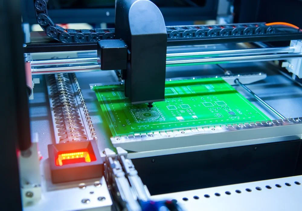
Automatic Equipment

Our advanced equipment and skilled technical workers ensure the quality and reliability of our products.

Quick Delivery

We strive to meet 100% of our customers' delivery deadlines and not make bad effect.

Why Choose Us as Long-term Partner?

We have the ability to dispose of tricky PCBs as a high-end printed circuit board manufacturer in this field for 19 years. 

Quality System

ISO9001 quality system certification, as well as ROHS certification, is fully implemented in our company.

IPC Standards

IPC-6012 standards are followed in the production of all boards and IPC-A-600 standards are used for the quality control.

Material Supply Chain

Utilizing raw materials from top 5 branded supplier, tailoring incoming inspection specifications

Competitive Prices

This is a short description elaborating the service you have mentioned above.

Request A Free Quote

Rigid PCB We Made for Customers

Products speaks for themselves. Please contact us to get your quotation and your first PCB prototype made by us. We believe we can become the most trusted and reliable long-term partner with you.